
Storage EPC: standalone and integrated battery systems, engineered to the requirement
Terragreen designs, integrates and deploys Lithium Iron Phosphate (LFP) battery storage systems for commercial premises, industrial plants and utility networks. Whether deploying an all-in-one unit for an office, modular indoor racks for a factory, or a multi-container grid asset, we size the battery around your load profile and backup duration first.
A Terrakraft India company. Equipment selected on technical and commercial merit. Configurable storage engineered in partnership with Zyntra, with domestic integration and a 15-year asset support commitment.
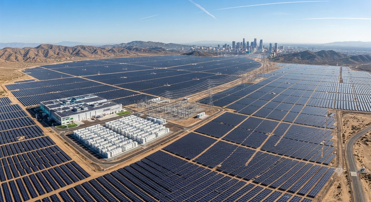
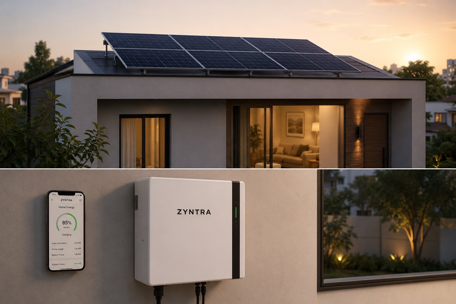
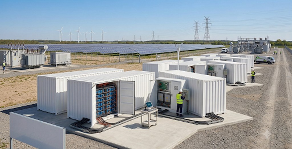
Platform specifications published by Zyntra. Final values are issued in signed datasheets.
We start with the storage requirement, not the solar panel layout
Conventional energy projects treat storage as an afterthought—a standard battery bolted onto a solar array. When loads surge or the grid fails, generic batteries trip or degrade rapidly under ambient heat.
Our method is storage-first engineering:
Load and autonomy profiling
We analyze your 15-minute interval demand data, peak motor start surges, and required backup duration.
Duty-cycle sizing
We configure cell series, inverter capacity, and depth of discharge around your specific operating duty.
Power-path integration
We engineer the protection, synchronization, and communication protocols into your existing HT/LT switchgear before specifying generation sources.
Storage can be deployed as a standalone asset to manage demand charges and backup power, or integrated into a hybrid solar and storage system.
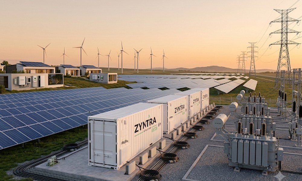
Energy that stays on.
We size the battery around your load profile and backup duration first.
From one premises to a transmission-level project
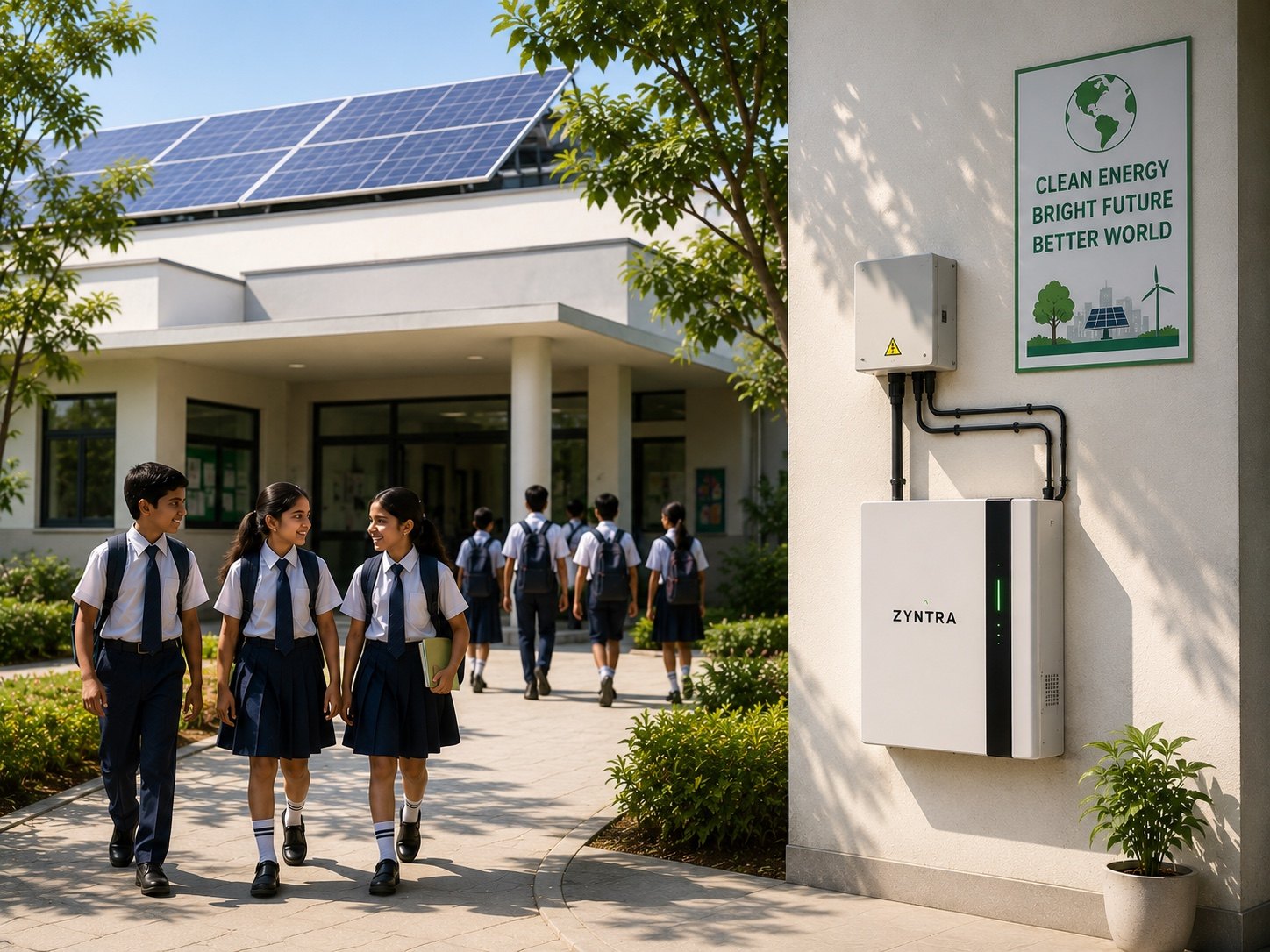
For offices, healthcare facilities, commercial branches, and residential estates
Built for indoor and perimeter installations where space is constrained and quiet, unattended operation is essential.
- Single-Unit Simplicity (ZyntraPOD): Combines the power conversion system (PCS), battery pack, and automated energy management system (EMS) in one pre-wired cabinet. No external components to match or cable on site.
- Indoor-Safe LFP Chemistry: Non-toxic, cobalt-free chemistry with a +270 °C thermal runaway threshold. Safe for installation in equipment closets, basements, or utility rooms.
- Silent, Uninterrupted Transition: Automatically carries essential circuits through grid cuts with zero generator delay, fumes, or fuel logistics.
- Automated Tariff Arbitrage: The internal controller charges during daytime solar or low-tariff windows and discharges during expensive evening peak hours.
For factories, warehouses, cold chains, and data-critical sites
Designed for behind-the-meter industrial deployment where high-draw machinery, air compressors, and process lines create expensive power demand spikes.
- Dynamic Peak Shaving: The system monitors incoming plant lines continuously. When large inductive loads start up, the battery discharges in sub-millisecond time, absorbing surges before they register on your contracted utility demand meter.
- Configurable Bill of Materials: Storage is built around your plant's specified voltage (415 V LT or 11 kV / 33 kV HT stepping), preferred inverter OEM, and physical floor footprint.
- Modular Expandability: Systems scale on a common DC bus. Add capacity in 10 kWh to 100 kWh increments as your production lines expand.
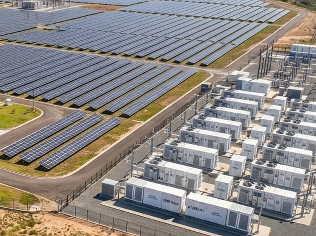
For substations, IPPs, grid firming, and transmission-level projects
Turnkey, outdoor-rated container systems engineered for utility interconnection, grid compliance, and solar-park co-location.
- Grid-Forming & Black-Start Capability: Inverters provide synthetic inertia, active/reactive power control (P/Q), and autonomous black-start to energize isolated networks without synchronous generators.
- Dynamic Grid Response: Fast frequency response within <20 ms to stabilize transmission frequency deviations and comply with grid codes.
- Pre-Tested Sub-Assemblies: Battery racks, internal HVAC, aerosol fire suppression, and PCS panels are factory-integrated and tested prior to dispatch, minimizing civil foundation and onsite termination timelines.
Built on a three-layer architecture: chemistry, control, and intelligence
Every storage system deployed by Terragreen operates on the same core engineering platform—from a 10 kWh commercial cabinet to a 40 ft utility container.
Layer 1: Chemistry (LFP)
We utilize stationary Lithium Iron Phosphate (LiFePO4) prismatic cells. Unlike cobalt-based chemistries (NMC), LFP's olivine crystal lattice undergoes negligible volumetric change during continuous cycling.
- Thermal stability up to +270 °C.
- 0% cobalt and 0% nickel content.
- Up to 95% usable depth of discharge (DoD).
- Rated for 8,000 cycles at 0.5C before dropping below 80% initial capacity.
Layer 2: Control (Hardware-Enforced BMS)
Safety is enforced at the physical hardware layer, independent of software or cloud connectivity.
- Dynamic cell-level voltage and temperature cutoffs.
- Sub-zero charge blocking prevents lithium plating on cell separators.
- Continuous active impedance balancing prevents cell drift across multi-rack strings.
- If local networking or external EMS software goes offline, the hardware BMS continues to enforce safety envelopes without interruption.
Layer 3: Intelligence (Sovereign EMS)
Our proprietary Energy Management System converts passive batteries into active, revenue-optimizing assets.
- Time-of-Day (ToD) Arbitrage: Automatically schedules charging during low-tariff or midday solar periods and discharges during peak tariff slabs.
- Open Industrial Protocols: Native support for Modbus TCP, DNP3, and IEC 61850 allows direct integration into existing plant SCADA systems.
- Telemetry Sovereignty: Operational telemetry and control logic remain securely within your enterprise firewall. No sensitive plant operational data is routed through third-party public clouds.
Enclosures engineered for Indian operating conditions
A battery system either withstands ambient summer conditions or silently loses operating capacity to thermal throttling. Terragreen enclosures are engineered as active thermal systems.
Directed Airflow Design
Conditioned cooling air is directed across individual rack faces from front to back, maintaining uniform cell temperatures rather than averaging ambient container volume.
IP55 / IP66 Weatherproof Steel Construction
Sealed against fine industrial dust, monsoon humidity, and ambient particulate ingress.
Central Service Aisle Architecture
20 ft and 40 ft containers feature an internal walk-in maintenance aisle with front-facing terminations. Field engineers inspect and service modules directly without dismantling entire series strings.
How energy storage delivers financial return
Storage is an investment in demand control and operational continuity. We model returns against your past 12 months of utility billing data using four levers:
| Vpeak | Avoided contract demand penalty charges (INR/year) |
| Varbitrage | (Peak tariff − Off-peak tariff) × Discharged energy (kWh/year) |
| Voutage | Avoided production loss and displaced diesel fuel expense |
| Coperating | System auxiliary power and maintenance contract costs |
Figures and formulas on this page are indicative and non-binding estimates. See the Disclaimer.
Modelled inputs
Time-of-Day tariff differential, contract demand limits (kVA), round-trip efficiency (typically >86% AC-to-AC), and auxiliary cooling consumption.
Measured baseline
Actual utility meter data, recorded maximum demand indicators (MDI), and generator logbooks.
If the numbers do not work
If your tariff structure or demand profile does not justify storage economics, our engineering team states that upfront during evaluation.
Clearly defined boundaries for storage EPC contracts
We delineate responsibilities in writing to ensure seamless execution between plant engineering teams and our project delivery groups:
| Project milestone | Terragreen scope | Client / site scope |
|---|---|---|
| System Engineering | Included Load profiling, storage sizing, single-line diagrams, protection coordination review, and thermal layout. | Supplying 15-minute load interval logs and single-line diagrams of the plant bus. |
| Equipment Supply | Included LFP battery racks, BMS, bi-directional PCS, isolation transformers, HVAC, and fire suppression. | Providing clean equipment room or outdoor civil foundation pad. |
| Site Integration | Included AC power terminations, control cabling, CT/PT metering connections, and EMS integration. | Scheduled plant shutdown window for final main bus tie-in. |
| Testing & Handover | Included Insulation testing, cell balancing verification, full-load charge/discharge testing, and black-start commissioning. | Operational team participation during commissioning sign-off. |
| Life Cycle Support | Optional Remote monitoring, scheduled preventative maintenance visits, and cell SoH tracking under an O&M Agreement. | Providing local internet/LAN access for encrypted telemetry relay. |
1,000-site distributed deployment record, delivered by Zyntra.
Frequently asked questions about our energy storage systems
Can a battery storage system be retrofitted to our existing solar plant?
Yes. We conduct an interface review of your existing inverters and switchgear to determine whether AC coupling at the plant bus or DC coupling at the inverter stage offers the cleanest electrical integration.
How does Terragreen select battery storage equipment?
Equipment is specified on technical and commercial merit. We offer configurable storage systems engineered in partnership with our sister brand Zyntra, which provides domestic manufacturing and tailored BoMs. Alternative tier-1 equipment is evaluated where project specifications require it, and all group relationships are disclosed.
What is the difference between the 5-year warranty and the 15-year support commitment?
The 5-year term is our comprehensive onsite product warranty covering cells, BMS hardware, and enclosure systems. The 15-year asset support commitment guarantees spare parts availability, engineering support, and firmware updates across the operational life of the installation.
What safety systems protect against thermal runaway?
Safety is multi-layered: inherently stable LFP chemistry (+270 °C runaway threshold), hardware-enforced BMS voltage/temperature cutoffs, directed rack-level cooling, and integrated aerosol or clean-agent fire suppression systems inside all enclosures.
Sizing storage for your facility
Share your facility's 12-month billing data, contract demand limits, or single-line diagram. Our engineering team will prepare an initial configuration and financial payback simulation.